Quantcast
Channel: CAD – SolidSmack
Viewing all 410 articles
Browse latest View live

Onshape In-Context Assembly Design is Unlike Anything You’ve Ever Seen

$
0
0
onshape-in-context-design-00

onshape-in-context-design-00

Presented by
collaboration in Onshape

Throughout all the years (decades? yeow!) I’ve use 3D modeling software, I can’t think of a time where I didn’t use some type of in-context assembly design. Not building out a design like that gives me the shakes – I honestly can’t grasp how to get accurate fit and function without it. “That there is what them there hammers is fer!” EXACTLY. You just go ahead a beat that fuel line into submission. I’ll stand waaaaaaay over here.

But there are valid reasons why people don’t want to use in-context design in traditional CAD software. Some companies actually ban it or require all reference be destroyed. Why? Simply put, errors, and the potential cost of those errors. The worst case scenario of in-context assembly design is when a part changes and that change trickles down through designs, drawings and manufactured parts. We may not even see an error in the assembly. But then there’s when we do get those errors; when the assembly just blows up with rebuild errors, missing references or corrupt design files. In traditional CAD, you’ll see this effect immediately when you move an in-context part in an assembly. We should flippin’ be able to move parts in an assembly without affecting their features!

Onshape has addressed all of this. ALL. OF. IT. Now, Onshape allows you to create an Assembly Context that gives you the 3D modeling super power of editing parts in context of the assembly WITHOUT all the pain mentioned previously. Pardon me.

With these Assembly Contexts:

  • Models always update in a predictable manner
  • Motion doesn’t affect in-context relationships
  • You can capture multiple Assembly Contexts
  • You can use them to edit single or multiple parts
  • You can update the Assembly Context if needed

The approach they’ve taken to implement in-context assembly design is exact, beautiful in fact, and captures the spirit of design in Onshape that already makes the modeling process such a smooth one. So, how did this feature take shape?

Long ago (last year)…

What’s a Part Studio?
A Part Studio allows you to create one part or multiple parts in a single context. A Part Studio may contain multiple parts, just like assemblies may contain multiple assemblies. It allows you to model an entire assembly that can be used in other assemblies or referenced in other Part Studios. To learn more about how Part Studio work, watch this video.

Onshape came out of beta with a unique way of working with multiple parts – Part Studios. Most people/companies I know don’t model multiple parts in a single part file… unless the part is a purchase part or used for reference. Most model each part and put them in assemblies (bottom-up), or model parts within the assembly to take advantage of referencing other parts (top-down). However, Part Studios are set up to simplify building parts together. If you know they’re related parts, you get some efficiencies by building them together in a Part Studio. For instance, edits are much more controlled and predictable.

However, you may not always be able to anticipate how parts will affect each other until they are assembled. That’s where Onshape’s new in-context design capabilities come in. So, how does that work? Let’s watch the video on the new feature first, then break down what sets it apart.


How Does In-Context Assembly Design Work in Onshape?

So, you have an assembly in Onshape. You need to add clearance between one assembly part and another. *record screech* Previously, you would sit back, pull on your neck skin and consider how to modify the part. Do you mock it up in the Part Studio? Do you measure it and transfer dimensions in the Part Studio? *grrrr* Either way, it’s not controlled by the part in the assembly. *GRRRR!* No more of that. Now, you can control every aspect of the part in the context of the assembly. Here’s how it works.

Back to our assembly in Onshape. You need to add clearance between one assembly part and another. In the assembly, right-click the part you want to edit and select ‘Edit in context’. The instant you select ‘Edit in context’, Onshape creates a snapshot of the assembly at that moment in time of your design, then opens the Part Studio. You’ll see the part you’re editing, of course, but you’ll also see any assembly part that was visible as a ghosted part. You can then start or edit sketches using those ghosted parts as reference for dimensions or constraints.

Here it is in three steps:

onshape-in-context-design-02
Activate In-Context Editing from right mouse button menu.
onshape-in-context-design-03
Select the part to edit and start or edit a sketch.
onshape-in-context-design-04
Add your dimensions with reference to other features.

However, this isn’t meant to replace or fix creating all parts together in a Part Studio or using the Derived feature. In-context features on Multi-part Part Studios or Assembly Contexts are  different, but complementary methods of a production level design environment. You’ve seen how Part Studios can be used. In-context assembly design is for when you don’t quite know design intent up front, when you do know design intent and want to drive assembly parts with other features, when you’re working with lots of imported parts, working on somebody else’s document, or working at the same time in the same document with others.

Here are just a few real-world examples where in-context assembly design gives you an advantage over bottom-up or multi-part design:

  • A bracket can be designed to connect two sub-assemblies
  • A latch keeper can be located and edited to account for interference or function
  • A tie-rod can be adjusted correctly to determine varying lengths
  • An entire assembly can be driven by a base feature

What Sets Onshape’s In-context Assembly Design Apart?

Along with a clean methodology of editing assemblies in-context, there are some very important aspects that set in-context assembly design in Onshape apart from any top-down, in-context design within other traditional CAD software. Because a database captures everything in your Document, that snapshot taken when an assembly context is made, that sucker is kept forever and does not change, which adds benefits you may have only dreamt about:

  • A context will NEVER be broken, or lost, and if it becomes outdated you can update it
  • Geometry of a part doesn’t change when the reference part is moved
  • If a design change is required you control when and how each context is updated
  • You can create a new Part Studio in context of the assembly
  • A part can be edited in-context of itself (multiple instances of the same part in the assembly – they interfere with each other and you want to correct it)
  • It’s feature agnostic. You can edit a feature created BEFORE the context was created and reference downstream features (circular references!)
  • If a part is used in multiple sub-assemblies, you can edit it in context of each sub-assembly, so the same part can be used in several different scenarios (although only works in current Document; support for linked Documents is on the roadmap).
Updating the in-context feature from the assembly.

During their first year, Onshape added a lot of great features – you can probably name the one that convinced you to give Onshape a serious go of it. If you work in assemblies a lot, the new in-context design feature may be that one for you. It does for me, as one of the must have features. It’s apparent the Onshape team took the time early on to think of these features and how they would work . Which, incidentally, makes me anticipate how they will implement some other features we’ve been waiting for–features I shall leave unnamed *ahem*. I can’t wait for those. But this, this is the feature that tips Onshape over to a production-ready, professional level software platform and I’m convinced any company that uses in-context assembly design will want to take a deeper look at Onshape.

The post Onshape In-Context Assembly Design is Unlike Anything You’ve Ever Seen appeared first on SolidSmack.


Model of the Week: Baby Groot [I Am Baby GROOT!]

$
0
0
baby-groot-3d-print-Michal-Miszta-00

baby-groot-3d-print-Michal-Miszta-00

Who needs a creepy, baby tree creature sidekick on their desktop? Oh yeah! I see those hands going up. I do too, but not just any creepy, baby tree creature. I needs me a BABY GROOT up in har!

Guardians of the Galaxy 2 is hittin’ theaters May 5th, so that gives you plenty of time to download this super sweet, super detailed model of Rocket the Raccoon’s muscle… or eventual muscle, BABY GROOT. Oh, and you KNEW there was gonna be a baby Groot in the sequel when you saw that adorable little potted stick with hands dancin’ at the end of the first one. GROOT. The best.

This version was designed and modeled by Byambaa Erdene in ZBrush and first printed using a Makerbot Replicator with a 20% infill. There’s a lot of great detail in this model and he’s provided a high-res version with “several million polygons” to bring it all out in your print. This is the first version of the model which has received a lot of praise online so far. Enough that Byambaa plans to bring out additional models, including new heads, a new body and more.

Byambaa has made the high-res version available as a free download here on Inov3D, but you can also grab it (or here on Thingiverse.) He’s also provided the low res version for download on Thingiverse as well.

The painting? I’m sure you can take that on just fine, but if you would like a reference, The Model Maker (maker of the lead image above) has a great write-up on the printing and painting of the model, down to the print specs, primer and paint numbers.

The Inov 3D Facebook Group also has LOADS of examples of people who have already printed this model. Here are some images from the group:

Print and paint by Brian McMeans
Print and paint by Jay Yuedol‎
Print and paint by Lauren Angers
Print and paint by Michael Crone
Print and paint by Michal Miszta
Print and paint by Mike Bogutsch‎
Print and paint by Mike Carr
Print and paint by Ross Leuck
Printed by Jake Jones

Have a model you think everyone needs? Share the link and details with us here!

The post Model of the Week: Baby Groot [I Am Baby GROOT!] appeared first on SolidSmack.

3 Adobe Apps to Ponder for the Future of 3D Product Design

$
0
0
adobe-max-stylit-3d-texture-lighting-00

adobe-max-stylit-3d-texture-lighting-00

Well, we’ve seen what Adobe is bringing to 3D and UX design, but Adobe Research has developed some other interesting apps, highlighting them at the 2016 Adobe Max conference. They cover the gamut, from 2D and 3D to voice and VR, leaving us with something to ponder on the future of 3D product design.

Bear in mind, Adobe has yet to announce any release dates for their (still in development) software apps, however they merit a rundown for the technological advancement the graphics software company is pursuing. With each of these, just imagine how it would/could/should apply to 3D modeling/design/rendering software. Let’s begin with a look at StyLit.

StyLit

Simply put, StyLit renders a 3D image based on what the user draws and colors in a real-time setting. Now here is the tricky part, the rendered image doesn’t necessarily need to be exactly what the user is drawing. For example, in the video Adobe’s Paul Asente grabbed an image of a dinosaur and rendered it into an artistic 3D image by drawing and coloring nothing but a ball, essentially porting his style to the digital representation. And it all happens in real-time. Amazing.

A camera situated over the drawing area captures the lines and colors with an algorithm mapping it to the 3D model. Even edits are ported to the image in a real-time setting and can be adjusted on the fly. It was published at SIGGRAPH 2016 by Jakub Fišer and team of Prague-based CTU with Adobe Research. A demo is now available at stylit.org.

VoCo

You’ve heard of putting words into someone’s mouth. This is exactly what that does. VoCo is being touted as ‘Photoshopping for Voiceovers’ and rightly so as the application allows you to edit speech using text by sampling a voice. Yes, you can recreate that sample voice to say anything you want just by typing the text into the VoCo editor, and it sounds identical to the sampled voice. Demoed at Adobe MAX by Adobe engineer Zeyu Jin, you’ll see how easy voice editing will become.

According to Adobe, it takes about 20-minutes for the software to analyze the speech audio and patterns before it can be edited with very few mistakes in the edited audio. Freakin’ scary and freakin’ cool. Could someone use my voice for trickery or something more malicious? In the video Zeyu states that there are safeguards in place and something akin to a watermark that would prevent others from doing just that. Unfortunately, there is no free demo that we can play around with just yet, but chances are we will see (hear) it at some point this year.

CloverVR

Another of Adobe’s previews is CloverVR. This app provides Adobe Premiere-style editing tools directly inside your VR video environment. The current process of editing 360° video requires the users to constantly mount and remove the VR headset–viewing, editing, viewing, editing… it’s highly inefficient. In the video, Adobe’s Stephen DiVerdi demonstrates CloverVR’s capabilities using an Oculus Rift to adjust the look-at direction for the transition between two video clips.

Using the app’s toolset, Stephen splices together two video scenes to focus on the action so that they appear relative to area you are viewing. You manipulate the editing tools in VR using the headset’s hand controllers rather than a keyboard, which seems to make the editing process easier to some degree. It also seems to provide a better perspective for editing 3D content as opposed to viewing it on a flat display. Again, there’s no word yet on when CloverVR or the other applications will be released so I will update this when it becomes available.

Adobe previewed quite a few different techologies, all approaching creative workflows a little, and often a lot, differently than usual. I recommend viewing them all. We’re hopeful we’ll see some of this sort of tech or, at least, this type of innovative thinking when it comes to our precious product development software and tools.

The post 3 Adobe Apps to Ponder for the Future of 3D Product Design appeared first on SolidSmack.

Onshape Goes Metal. Sheet Metal.

$
0
0
onshape-simultaneous-sheet-metal-design-00

Use Onshape? Well, there’s a reason why, today, your coffee is tasting especially good, why your underwear seems to fit a little better, and why you don’t have to pretend Onshape has sheet metal tools anymore… because now THEY DO. Onshape just announced sheet metal.

They’re out at the Pacific Design and Manufacturing Show where they’re previewing the new sheet metal capabilities currently finishing early visibility testing and landing with the next big update. Apparently, they’re a bit ambitious this year, with this coming right on the heels of another huge feature addition, in context assembly design, which allows you to create and edit parts in the context of other assembly parts, without contexts being broken or model geometry changing when moved.

onshape-simultaneous-sheet-metal-design-01

The sheet metal video (gated), shows a complete rethinking of sheet metal design, and when you see how it works alongside in-context design, I think you’ll agree the approach is brilliant. Here’s the breakdown:

  • Create a sheet metal part by converting a solid, extruding a sketch or thicken a face.
  • Part Studios allow multiple sheet metal parts built together or ripped into multiple parts.
  • Simultaneous Folded, Flat and Table Views, all calculated in real-time.
  • Explicit feature control automatically adds reliefs/features even if traditional tools used.
  • Table view can be used to edit bend radius, order and angle.
  • Works with collaboration, secure sharing, version control, branching/merging, and full restore abilities.
Simultaneous Folded, Flat and Table Views that update in real-time.

When you make a change in one of the sheet metal views, the other two views update right along with it. If there’s a flange interference in the flat view, you see it right away–no setting up configurations or creating and switching to drawing views to see what works. And the table view allows you to go through and change bend order, radius or angle, instead of navigating through features to make simple changes.

Many of the other sheet metal options you’ll be familiar with, from setting edge clearance, relief type and k-factor to creating flanges, joints, and corners. Miters can be created automatically, rip style can be set with a simple selection and all along the way, you see the flat pattern update as you make it.

Outside of surfacing, I don’t think there’s a more anticipated feature for Onshape than sheet metal. In my last job, there wasn’t a day I didn’t have to get flat patterns out to the shop. Oh, the time that could have been saved. *sigh* Now, with Onshape’s FeatureScript, I’m curious to see if a nesting process or sheet metal features can be automated.

I think Scott Harris, Onshape’s VP of Product Definition and User Experience, captures the impact their approach to sheet metal is going to have:

“Part of the beauty here is that you can start down one path and if things aren’t right, you can just change it around without having to start over again. In fact, you can refactor your model by switching around rips and bends.”

“This is going to prevent a lot of headaches between designers and manufacturers, because almost all sheet metal work is done collaboratively. We created the system to allow designers to build in design intent and allow fabricators to adjust the model based on specific tooling, without violating the design intent.”

I’m sure we’ll be taking a deeper look at Onshape’s new Sheet Metal capabilities in the future. Until then, check it out and let us know if it’s all you hoped and dreamed.

onshape-simultaneous-sheet-metal-design-02

onshape-simultaneous-sheet-metal-design-03

onshape-simultaneous-sheet-metal-design-04

onshape-simultaneous-sheet-metal-design-05

onshape-simultaneous-sheet-metal-design-06

The post Onshape Goes Metal. Sheet Metal. appeared first on SolidSmack.

Autodesk CEO Carl Bass Steps Down, Spending More Time With His Robots

$
0
0
carl-bass-ceo-autodesk-shop-00

This is right out of the blue. As of today, Carl Bass is no longer CEO of Autodesk. His 10-year stint as the San Fransisco-based company’s leader ends after transitioning the company to the cloud and subscription based product offerings, launching an open hardware platform, overseeing 30+ acquisitions and building Pier 9 workshop to help drive and nurture the passion behind it all.

Back in 2006 when Carl took over as CEO of Autodesk, he was named by then-CEO Carol Bartz as her replacement. Carl’s departure sees no new CEO named. Only that day-to-day operations will be overseen by Amar Hanspal, Senior Vice President and Chief Product Officer, and Andrew Anagnost, Senior Vice President and Chief Marketing Officer, as interim Co-chief Executive Officers. This may seem odd, but was a decision reached by the Autodesk board of directors, on which Carl will still be serving with a nomination for re-election to the board at the 2017 annual meeting of shareholders.

A letter to employees was published on Autodesk’s In the Fold blog, where Carl thanked everyone from Mrs. Bartz and shareholders to partners, customers and employees. He left everyone with the few words you may have heard him mention over the years, words he used to describe Autodesk and, I think if you look deeper, his own role in what they achieved.

“When I first became CEO, people asked how I wanted to define Autodesk and I often answered somewhat cryptically, ‘great, good and important.’ In my mind, great companies are defined, first and foremost, by their financial performance. Good companies are defined by their values and culture and how they treat their employees, their customers and the communities in which they do business. And important companies make a real difference in the world.”

He left a lot to the imagination with no detail of his plans from this day on, except to imply he’ll be spending plenty of time at his workshop in Berkeley, California. I don’t quite blame him.

“I am not leaving to spend more time with my family—that presumes my family wants to spend more time with me. I will, however, be spending more time in my shop with my robots. I also have some other plans and will have more to say on what I’m doing in the next few months.”

I asked Carl what he’s working on first. He says, “The first thing I’m working on is using machine learning to figure out how to drive my son’s go kart autonomously. It’s a very cool project in which we’re training it with data coming out of a video game we built. Also, been finishing up the renovation of my metal shop and building lots of stuff for the shop including this very cool folded metal staircase (fusion sheet metal showed up just in time).”

Al, Rita, looks like we’ll have to find another CEO for 2AM drinks in Vegas.

Lead Photo Credit: James Martin, CBS

The post Autodesk CEO Carl Bass Steps Down, Spending More Time With His Robots appeared first on SolidSmack.

Model of the Week: RC Speed Tank [Roll Out!]

$
0
0
rc-speed-tank-3d-print-model-solidsmack-00

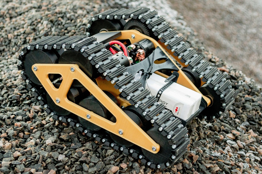
It’s embarrassing isn’t it? When you get caught in the garage with all the tires off, halfway between blowtorching the lower panels and wrapping tank tread around your freshly welded drive sprocket. Just tell your spouse the smell will dissipate over time. Then, quickly show them RC Speed Tank this to distract them.

Sven Drechsel has created a very simple RC tank project with the majority of the parts, even the tread, 3D printed. The rest of the projects involves some very basic electronics and screw-together assembly. This is a great beginner project for 3D printing and electronics, or for anyone interested in making a fun little RC toy. Since it’s a ‘Speed Tank’, you can bet it goes fast. How fast does it go? Sven says it’s a durable 25 km/h (15 MPH). Not too shabby! Here he is showing what it’s capable of IN THE SNOW.

You can download all the files on Thingiverse. The details and part list is in German, but you can find the translation below with parts sourced in the USA. There isn’t much in the way of schematics or assembly instructions, but the assembly .stl will get you half way there.

Part List

2X 540 35T engine and 60A Brushed ESC 2X Pinion Gear (Module 1 / 11 teeth)
2X Pinion Gear Adapter 5mm to 3.2mm
12X 8x22x7mm 608 Ball Bearings
12X 4x13x5mm 624 Ball Bearings
2x 2200mAh LiPo Battery
1X Flysky 2.4GHz 6-Channel Transmitter/Receiver

Screws:
M4x15mm 8x
M4x60mm 12x
M3x20mm 4x
M3x10mm 4x
M3x45mm 84x

Nuts:
M4 20x
M3 88x

3D Printed Parts

2X Drive wheel
1X Basic plate
1X Front Bumper
1X Rear cover
84X Chain link
2X Caster chain tensioner
8X Caster
1X Side part mirrored
1X Side section
1X Stiffening mirrored
1X Stiffening

Assembly

Everything is designed to be screwed together and modular for easy assembly/repair. The nut locations are designed to be press fit for quick installation. Depending on your print setting and material shrinkage, the bearings should also press fit.

The 42 chain links are connected with the M3x45mm screws, then secured with M3 nuts, which can also be secured with an anchor or glue. The “caster chain tension” adds tension to the track assembly and is mounted at the foremost caster since it’s a different size.

Print support

Part support is only necessary for the Caster, Caster Chain Tension, Drive Wheel, and Baseplate.

Have a model you think everyone needs? Share the link and details with us here!

rc-speed-tank-3d-print-model-solidsmack-01

rc-speed-tank-3d-print-model-solidsmack-03

The post Model of the Week: RC Speed Tank [Roll Out!] appeared first on SolidSmack.

RedLine For SOLIDWORKS Add-In Finally Gives Your Mark Up Capability Inside SOLIDWORKS

$
0
0
infinitydraw-redline-solidworks-add-in-01

Anyone familiar with SOLIDWORKS, or 3D CAD in general, knows you can’t easily markup a 3D model or drawing within the software. You still need to print the drawing or model, hand-deliver it to the conference room, shop floor or the friendly checker grinning at you expectantly over the edge of the cubicle. The. Joy.

The new RedLine add-in for SOLIDWORKS from InfinityDRAW changes this, allowing you to digitally redline your parts, assemblies and drawings right inside SOLIDWORKS. The potential time and money this saves alone is huge, not to mention the paper, ink, trips to the pen cabinet and energy of sorting through different redline stacks. It also addresses the lack of redline capability in SolidWorks but goes a long way toward alleviating the miscommunication that inevitably happens with paper redlines.

infinitydraw-redline-solidworks-add-in-01

There are actually two add-ins available –RedLine for SOLIDWORKS and RedLine for SOLIDWORKS PDM. RedLine for SolidWorks allows you to markup models on virtual surfaces or, as you’re used to, on the drawing sheets directly. RedLine for SOLIDWORKS PDM adds the capabilities to SOLIDWORKS PDM to markup eDrawings, SOLIDWORKS or Draftsight files, but also adds real-time redline notification, markup history and digital signoff — perfect for managers, manufacturing and drawing checkers ready and willing to lather your drawing with red.

infinitydraw-redline-solidworks-add-in-02

The markups stay with the SOLIDWORKS file as well and PDF redline reports can be generated with links to the affected files. The markups will also be retained if/when the file is printed. A mouse isn’t the easiest tool for writing or sketching redlines, but can be used. However, this just reinforced the use of touchscreen/stylus combos or Wacom tablet use for CAD.

There are no prices listed for the add-ins, but we’ve reached out to InfinityDRAW for pricing details. You can request more information via the InfinityDRAW website.

Clear, unambiguous communication is absolutely essential in an engineering environment. It’s amazing it took this long for something so integral to the product dev process to show up. Eventually… hopefully, we’ll see more workflow add-ins like this added to the CAD software of the future.

infinitydraw-redline-solidworks-add-in-03

The post RedLine For SOLIDWORKS Add-In Finally Gives Your Mark Up Capability Inside SOLIDWORKS appeared first on SolidSmack.

3 Features That Make Fusion 360 a Powerful Engineering Tool

$
0
0
fusion-360-simulation-3-things-01

Presented by
image05

I know, I know. I sealed off simulation with the 5 reasons I would use Simulation in Fusion 360 months ago. You thought we were all done with that. Well, you were wrong, Mwahaha! After that article, Autodesk released an update to Fusion 360 with so many Simulation features it could make a steel I-beam pucker.

To get to the heart of this massive update, and go beyond my simple understanding of Fusion 360 Simulation in general, I talked with Vikram (Vik) Vedantham, who I’m certain can calculate the deformation of an unladen swallow’s wing in flight within an instance of a giggle and a sip of fine chianti. Vik is Senior Business Manager – Fusion 360/Simulation, and when I asked him why go down the route of adding advanced simulation features, I wasn’t ready for his answer.

“There’s a growing need to answer engineering problems as part of the design process, regardless of industry or application,” Vik told me. Ok, I was ready for that, but not for this. “The product innovation platform is being structured to help manufacturers have all the tools necessary not just to design, but ENGINEER products. The vernacular of Advanced Simulation is only a hat-tip to the industry precedence. The technology being built into the product innovation platform is more of an engineer’s tool, and will continue to evolve in that direction.”

I don’t know about you, but a design tool is exactly the way I looked at Fusion 360. It’s sort of a paradigm Fusion 360 is slowly crushing. Whenever doing any sort of analysis in the past, it was always a different software and always took time, with changes leading to decisions like, ‘just double up the fasteners on every side’ instead of pushing it through another round of analysis.

That. Ugh.

That right there is the time where I wish I would have had a simulation tool to ‘just show’ instead of ‘just double up’. But, as Vik implies, the goal is to create a shift in mindset from Simulation as a validation tool, to Simulation as a solution to create, engineer and optimize throughout the design cycle. In other words, it’s that paradigm-crushing goal to be a guide to engineering design decision-making.

With that. Here’s where Fusion 360 Simulation reveals the difference between design tool and engineering tool.

  1. Shape Optimization

Shape Optimization is a “state-of-the-art conceptual engineering” feature of Fusion 360 Ultimate that shows you where you can remove material based on set mass, loads and constraints. I asked if it’s like spraying a firehose at a chunk of clay, seeing where it collapses first, and they just shook their heads. Unlike that, Shape Optimization helps you solve two problems, both of which involve that initial design decision:

  1. Starting a new design – Acts as a guide and helps eliminate barriers to progressing in the design.
  2. Using an existing design – Allows continuation of familiar workflow through optimizing and lightweighting existing designs.

I don’t know about you, but I’d like to lightweight a bag of chips right about now. It’s not always apparent, but this is a big advantage, i.e. the decision of where to start and the associated cost of change. It’s extremely critical to start in the right direction, and we have all sorts of kick-off meetings to attest to this.  But imagine going to those meetings with design exploration already complete; Exploration beyond what an engineer or a team of engineers can fathom within their range of skills, experience and expertise. It’s a process that takes minimal setup and certainly becomes quicker to setup over time. You build your body, set your constraints, and regions to preserve, and offload it to the cloud.

  1. From Concept Design to Engineering Product

So, simulation for conceptual engineering makes sense, right? But what about the rest of the process? The detailed design, the conditions, even the manufacturing variables. That’s where the simulation technology in Fusion 360 is built to serve as a ‘GPS’ for product development, guiding decisions through throughout the design, allowing you to examine the conditions as the design nears manufacturing and beyond.

“Designers and engineers must factor in the operating conditions to design for durability and sustained performance,” Vik explains. “Will my design carry a dead load without failing? Will my design overheat? Will my design face excessive vibration? Will my design permanently deform? Will my design collapse? What happens under impact? Fusion now has an elaborate range of options to determine all of this.”

  1. Simulation for Everyone

There’s part of me that’s a bit uncomfortable with the idea of ‘simulation for everyone’, as are a few PEs out there as well. There is a myriad of arguments around who should be using Simulation, but one thing I think everyone can agree on is an understanding of simulation (or rather, the outworking of simulation) is extremely important.

Let’s not get hung up on that, though. Autodesk is looking at providing a complete tool that captures all aspects. Vik says, “Ease of use is at the core of Fusion 360. That idea continues into Simulation, with the goal making the tech simply an extension of the design process.” They want everything to be ‘a click away’ so once you’re in, you realize you’re a step away from understanding how your design behaves.

On top of this, it’s not only Simulation for everyone, it’s Simulation that uses the Nastran Solver. You know the one widely regarded as the gold standard in automotive and aerospace industries? Yeah, that’s kind of available to every Fusion customer now.

Those three things, along with our other five, set Fusion 360 apart as a tool that can be used as an Engineering tool. You get the collaboration and online result sharing right along with it. The added ability to offload to the cloud-based solver can’t be underestimated, though. With that, you have simultaneous solving that frees you up to continue working and, my fav, no need for IT support.

You might think that utilizing all this cloud power costs a fortune. However, Autodesk has set it up so you pay for only what you use, instead of dealing with high upfront costs. According to Autodesk, for the majority of engineers depending on the cloud as part of their workflow, the cost of leveraging the cloud in tandem with concurrent engineering is likely to stay well below the traditional investments. Of course, the new simulation technologies are just one of the nine major components that make up Fusion 360. You can get a better idea of the other features and compare Fusion 360 Standard and Ultimate here. Beyond this, interested to know what you all find interesting about Fusion 360 and what you’re wondering about the most. Anything we should have a look at?

The post 3 Features That Make Fusion 360 a Powerful Engineering Tool appeared first on SolidSmack.


Vention.io is a Web-based Machine Builder Platform & Social Marketplace

$
0
0
vention.io-3d-web-machine-builder-platform-00

A Montreal-based startup is about to shake the world of design automation. Vention, a new browser-based machine builder platform, launched in beta today. They provide a social marketplace of industrial equipment for purchase and a 3D machine builder with library of components to construct your own equipment.

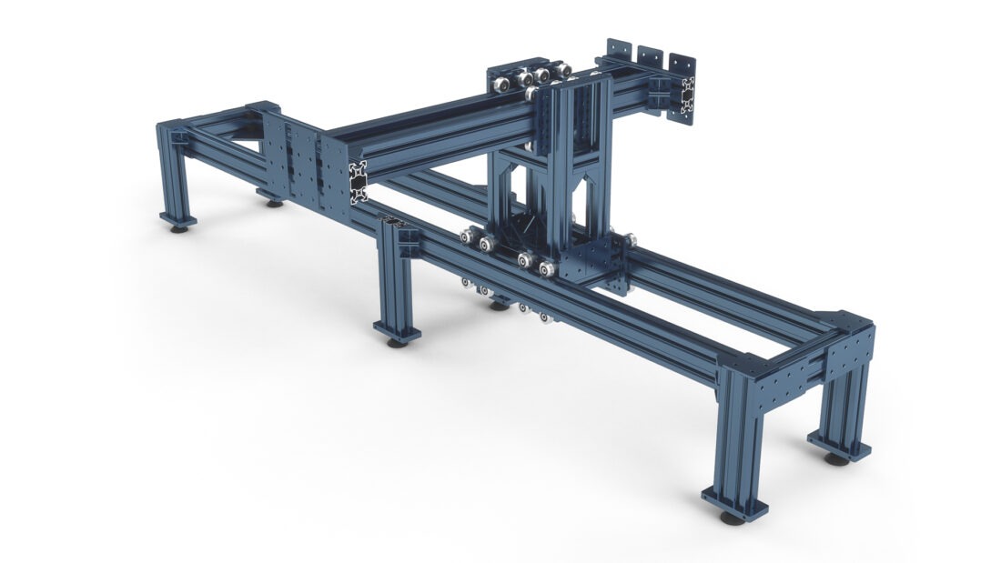
The platform and 3D machine builder is 100% free to use. (The company relies on the sales of the products for revenue generation.) You can log in, immediately start adding parts from a library of pre-defined structural, motion, control, and hardware parts and components. The interface allows a drag-drop-and-snap in place method of assembling any type of structure through an AI-enabled 3D constraint system. As parts are added, all cost and weight is calculated in real-time and shown on the screen with fastener requirement calculated automatically.

On top of this, designs published to the public can be used as a starting point, modified or re-configured. New assembly designs can be started collaboratively, invitations set to additional collaborators or private groups set up. Download of the 3D part or 3D drawing file is available for offline design and download of the 3D assembly is available from within the machine builder.

vention.io-3d-web-machine-builder-platform-01
The Vention 3D Machine Builder interface with drag-and-drop library of parts and components.

When talking with Etienne Lacroix, CEO of Vention, he explained that this isn’t 3D modeling software, but a whole new way of building assemblies for both professional CAD users and non-professionals alike.

“It became obvious to us that the next frontier for faster machine design wasn’t better design tools or higher performance hardware, but rather the integration between the two. The launch of our beta program is a first step in enabling our partners to experience a novel design and build workflow that will accelerate the machine design process more than 5-fold.”

Inside of this is a complete elimination of any 2D drawings or manual BOM management–it all happens automatically–and Vention is driving it all with a heavy focus on artificial intelligence both in the builder and the marketplace, a system built to constantly learn.  Here’s what the beta version of Vention platform includes:

  • A library of structural, motion, and control components.
  • A free cloud-based 3D Machine Builder.
  • Artificial intelligence-enabled 3D constraints
  • Real-time cost and weight in the 3D Machine Builder environment.
  • Automatic fasteners and bill of material management.
  • Access to a library of user-generated public designs.
  • Invitation of individual collaborators to a design.
  • Ability to set up a private design group.
  • Submission of new component ideas.
  • Personalized assembly instructions with purchase orders.

The company received an unspecified pre-seed round of funding led by Bolt and Real Ventures, along with some familiar names in the 3D software scene, Jon Stevenson, former exec at PTC and GrabCAD, and Rob Stevens, former exec at GrabCAD and Amazon Robotics.

I’m fascinated by the 3D machine builder and the technology behind it. It’s the most advanced 3D product assembly interface I’ve seen and, I believe, is a great example of the shift we’ll see in 3D product development over the coming years. The applications for this spread far beyond machine design, but Vention has started out with a focus that hits a wide set of industries where custom equipment builds are constantly needed in a sector no one else is thinking about. Keep an eye on this company and the tech they’re developing.

Library part with ability to add to your own design, purchase, download and comment on.


vention.io-3d-web-machine-builder-platform-02

The post Vention.io is a Web-based Machine Builder Platform & Social Marketplace appeared first on SolidSmack.

Model of the Week: 3D Printed Quadruped Robot [Four Times the Awesome!]

$
0
0
3D-Printed-Quadruped-Robot-00

Glory be! I’ve always said I wanted a baby quadruped of my very own. Those gang members with knives laughed, but I still kept saying it. After I got them all shirts with a cute baby quadruped graphic on it, they stopped trying to cut me. Just goes to show you Huey Lewis & the News, that’s The Power of (Quadruped) Love.

And this quadruped by Instructables user Toglefritz (aka Scott), is sure to stir the emotions of anyone. It. Is. Muy fabuloso, vato. According to his photos, it’s the size of a large cat, and each of the four legs has a full three degrees of freedom.

3D-Printed-Quadruped-Robot-04

He has the whole project laid out, step-by-step, and includes assembly animations and videos–it’s one of the finest guides I’ve seen on Instructables. He provides the list of purchase parts (and links), the code libraries and, of course, the 3D model files (iges and stl) he created using Fusion 360.

All together it’s made up of Lynxmotion Botboarduino, a SSC-32 Servo Controller, 12 Hitec Servo, a 16 LED NeoPixel Ring, and 38 3D printed parts, all controlled via a modded wireless PS2 controller. Scott had his printed via 3D Hubs by a local printer and shipped out to him.

He goes into great detail on each step of the build and has some great tips along the way that are sure to help you with other builds. You can download the model on Github and follow the Instructable here.

Have a model you think everyone needs? Share the link and details with us here!


3D-Printed-Quadruped-Robot-04

3D-Printed-Quadruped-Robot-03

3D-Printed-Quadruped-Robot-01

The post Model of the Week: 3D Printed Quadruped Robot [Four Times the Awesome!] appeared first on SolidSmack.

TurboSquid Launches New 3D Model Standardization with StemCell

$
0
0
feature

feature

It’s become so common in our workflows that we usually don’t even think about it anymore. But let’s be honest here: working with different 3D file formats between all the various tools we use these days is a royal pain in the ass.

But what if working with 3D files could actually be seamless? What if a 3D model created in one 3D modeling application could work smoothly in others? What if, like Apple said once upon a time, “it just works?”

With the launch of StemCell this week, that’s exactly what TurboSquid has in mind as we move yet another step further into the next generation of 3D content.

At its core, StemCell is a platform for making the buying and selling process for stock 3D models as easy as using stock photo and video; the content works seamlessly (in theory) in whichever app is being used by the creator for typical PBR workflows. Ultimately, what this means is that the frustrating art of managing file conversions between 3D programs is on its way out the door.

StemCell-01

“Ultimately, our goal is to make buying and using a 3D model as painless as using a stock photo,” explains Matt Wisdom, TurboSquid CEO. “The demand for accessible 3D content is growing – we saw major companies like Microsoft and Adobe release new tools this past year aimed at making 3D easier for everyone to use. We are in a unique position to speed that process up by standardizing a huge library of 3D models.”

StemCell-2

The first group of TurboSquid StemCell artists has begun submitting models built in Max or Maya (with V-Ray) to outputs in Max, Maya, Unreal and Unity. Support for Cinema4D, Blender, Stingray, Lumberyard, Arnold, Mental Ray—and others are coming later this year.

Try it out for yourself over at StemCell.

The post TurboSquid Launches New 3D Model Standardization with StemCell appeared first on SolidSmack.

Model of the Week: 3D Printed Carabiner [Belay On!]

$
0
0
3d-printed-carabiner-00

Like most somewhat avid outdoorsmen, I’ve gone rappelling once or thrice. After ending upside-down thinking I saw mountain lion preparing to devour me, I did the only thing you can do in that situation… scream while trying to cut yourself free from the carabiner holding you safely 50 feet over jagged rocks.

Now, I’m not sure I would use a 3D printed carabiner to hold me off a rockface, but if I did, it would be one of these from , who specializes in 3D printed carabiners. They have some incredible designs, both in metal and plastics (just check out their gallery), and they’ve shared two of their coolest designs with the Thingiverse community.

The Origami Carabiner is a two-piece print, hook and door, designed for an FDM 3D printer in PLA or ABS material. No support is needed and each one takes around 45-100 minutes to print. Alternatively, Nylon and POM can be used for ultra-strong results.

Some have scaled it down for work ID badges and some have scaled it up just to have an obnoxiously oversized carabiner. Me? I’m printing this to hang electrical cords and also a mountain lion skull… and some bags of beef jerky. Getting ideas, aren’t you? Here’s a breakdown of how the carabiner assembles and functions.

You can download the model on Thingiverse and see more of their designs on their site. (Bonus! Snag this Strong Flex door carabiner too!)

Have a model you think everyone needs? Share the link and details with us here!

3d-printed-carabiner-01

3d-printed-carabiner-02

3d-printed-carabiner-03

3d-printed-carabiner-04

3d-printed-carabiner-05

The post Model of the Week: 3D Printed Carabiner [Belay On!] appeared first on SolidSmack.

Get Fusion 360 at 50% Off + 3 Months Pluralsight Training

$
0
0
Autodesk-Fusion-360-00

Deal of the day folks. Over March 15th and 16th, Fusion 360 is $150 (50% off) for an annual subscription. This offer also includes 3 free months of Pluralsight training.

If you’re not familiar with Pluralsight, you need to be. They have thousands of courses, not only for 3D design software, but for other software you (like us) are probably interested in. They have monthly and annual memberships, as well as team plans.

Make sure and read the terms though. The deal is good for March 15th and 16th only.

This promotion offers a 50% discount on a purchase of a new 1-year subscription to Fusion 360, made 3/15/17 through 3/16/17 from the online store.

This promotion also offers a 3-month trial subscription to Pluralsight with the purchase of a new 1-year subscription to Fusion 360. AUTODESK IS NOT THE MANUFACTURER OR DISTRIBUTOR OF PLURASIGHT, AND AUTODESK MAKES NO REPRESENTATIONS OR WARRANTIES WITH RESPECT TO PLURASIGHT.  PLURASIGHT IS PROVIDED “AS IS” AND AUTODESK IS NOT RESPONSIBLE FOR DELIVERY OF 3 MONTH SUBSCRIPTION TRIAL OFFER FROM PLURALSIGHT. On completion of qualified Fusion 360 purchase, further details for accessing the 3-month trial to Pluralsight will be emailed to the purchaser.

The post Get Fusion 360 at 50% Off + 3 Months Pluralsight Training appeared first on SolidSmack.

Model of the Week: Your Very Own Pangolin [It’s Like a Armored Anteater!]

$
0
0
pangolin-3d-print-00

You can stop looking for the endangered animal you want to 3D print, because I found it for you. It’s a Pangolin. “A pango-what?” A pangolin. It’s a small, nocturnal mammal covered in protective scales and native to parts of Africa, China, India and Malaysia. Not only is this a 3D printed pangolin, it’s a 3D printed, papercraft-style pangolin, which makes it extra cute and not so creepy looking as a real pangolin.

What do you do with a 3D printed pangolin? Me? I want to print 50 of these, walk down a crowded street, fall on the ground and pretend they’re escaping from my stomach cavity. What? That’s not gross. “You’ll scare children!” Impossible. It’s a know fact that all children LOVE pangolins.

This model was made by Taiwanese designer and art creator, Chen Xuejian (Amao). He learned about 3D printing in 2015 and applied it to his interest in papercraft. Since then he has translated a few paper shape works over to 3D geometry to print them out. The pangolin is the most aggressive of his efforts, creating an articulating body which allows the model to stand, squat, raise its head and roll into a ball.

Amao used SketchUp to model the creature and an Up Plus 3D printer to print the model in ABS with a Z-resolutions of 0.2mm (0.25mm suggested for Cura users). All .stl files are provided.

A lot of people in the comments are raving about this print so really looking forward to this one. You can download the 3D model on Thingiverse or over on MyMiniFactory.

Have a model you think everyone needs? Share the link and details with us here!

pangolin-3d-print-01

pangolin-3d-print-02

pangolin-3d-print-03

The post Model of the Week: Your Very Own Pangolin [It’s Like a Armored Anteater!] appeared first on SolidSmack.

The Heatbuff Keyboard Heater Wants to Solve Icy Fingers Once and For All

$
0
0
feature

feature

It’s very much a first world problem, but a problem that plagues desktop workers all the same: cold hands.

While the problem is more prevalent for computer gamers, cold hands are a very real problem for those who sit at their workstations all day—in fact, it’s just plain science. As a result—whether the office thermostat is uncomfortably cold or not—we’re left with icy fingers that can make typing an email or powering through those keyboard shortcuts more of a pain than it needs to be.

Well, there’s a Kickstarter for that, folks.

The Heatbuff is a literal keyboard heater for keeping those icy fingers toasty. Billed as the ‘Future of gaming and workstations’, the infrared finger heating system is designed specifically to increase keyboard performance:

With $33,253 raised of their original $10,885 goal, it looks as though these guys just might be on their way towards creating the best desktop accessory of all time. You can get yours for $71 (before it bumps up to $100) if you support the campaign before April 7, 2017.

The post The Heatbuff Keyboard Heater Wants to Solve Icy Fingers Once and For All appeared first on SolidSmack.


Model of the Week: Sci-Fi Wall Tiles [Glue Them To Yo’ Face!]

$
0
0

Gheee! Are you seeing these? ARE. YOU. SEEING. THESE. This is not the exterior of the [insert name of random sci-fi ship or planet size weapon]. It’s a 3D printed array of sci-fi style diorama tiles that have more applications than Darth Vader’s cape.

The sci-fi diorama tiles by Roy Ang are 1/72 scale – each is 75mm x 75mm x 15mm (3″ x 3″ x 0.6″) and weigh approximately 80 grams. Given that it takes 1-2 hours to print, you could have a 10-foot section of wall covered in ONLY 1,280 hours. If you want a smaller area, say, YOUR FACE, you’re probably looking at 8-12 hours depending on resolution, the size of your mug and the complexity of your jowls. (I think I could model and machine a metal sci-fi mask in less time. Ahem.)

There are 14 different designs to choose from, but best of all, this provides the inspiration for so much more. Like making a sci-fi planting pot or a sci-fi beer can holder. HELLO! You can download these bad boys at MyMiniFactory. (Bonus: Check out Roy’s AT-AT Foot! 1/48 scale, which is perfect to embed in your wall to hang your jawa cosutume on. Utini!)

Have a model you think everyone needs? Share the link and details with us here!

3d-printed-sci-fi-wall-tiles-01

3d-printed-sci-fi-wall-tiles-02

3d-printed-sci-fi-wall-tiles-03

The post Model of the Week: Sci-Fi Wall Tiles [Glue Them To Yo’ Face!] appeared first on SolidSmack.

Top 3 Onshape Updates: Move Face, Offset Surface, Sweep Path

$
0
0
onshape-whats-new-features-1702-00

We’ve taken a broader look at Onshape and even talked about some lesser known Onshape features.  The company is pouring out an update every few weeks – some big, some little – that, combined together, speak to the agile nature of the company and how they develop solutions around someone’s ability to install and understand their software, but also how teams manage, analyze and collaborate on their projects.

You can see the history and catch the latest updates on the Onshape What’s New page, but we’ve had some interest from readers and discussion around keeping closer track of the Onshape features, breaking down the latest, pointing out our favorites and highlighting the ones we think push ahead product dev for CAD in the cloud.

We’ll attempt to have a ‘Top 3 Onshape Updates’ and a quick overview of the others. Tell us which one you like the best, which need work, or if we picked the completely wrong features!

The Stats:
Total Updates: 10
Total Updates YTD: 32

Top 3 Onshape Updates (03.03.17)

Move Face Up to Entity – Yes! Specify an entity to move up to with an optional offset.

Copy/Offset Surface – Yay! You can now copy surfaces or create offset surfaces using all the capabilities of the Move Face feature.

Sweep Path – Yawzow! The profile plane can intersect the path at any location with a sweep path feature.

Other Updates

@mentions – Use ‘@’ and a user’s name to comments to automatically share and notify other people.

Custom Properties – A new custom property editor to modify properties, add new custom properties, or set up required properties.

Add Properties to Notes – Custom Properties can be added to drawings as notes or in a title block.

Measurement Precision – Click and view display precision that is matched to the document settings.

Sheet Metal Ref and Bend Lines – Sheet metal parts can be referenced when designing other parts. Bend lines are automatically generated in flat view and drawing. (See more on their sheet metal here.)

Threads, Sharps and Quadrants – Better display and selection options for these items.

File Import – Support for SolidWorks 2017 and CATIA V6R2016x.

You can see videos that breakdown each new features here. So, what do you think? Good set of updates? It was hard not to put the new sheet metal updates and custom properties in the top 3.

Ask questions and talk about Onshape on SmackTalk!  Our new community site!

The post Top 3 Onshape Updates: Move Face, Offset Surface, Sweep Path appeared first on SolidSmack.

Model of the Week: Life-Size Alien Facehugger [Get it Off!]

$
0
0
full-size-3d-printed-alien-facehugger-00

The Alien Facehugger. It seems innocent enough… You know, after it chases you down, wraps its legs around your face, paralyzes you for a few days and falls dead off your swollen gnoggin–after that. We won’t go into the details of what happens next. What’s that? You’ve not seen any of the Alien movies? FOR SHAME. To think you’ve gone so many years without horrible nightmares and the voice of Bill Paxton in your head. “Game Over Man, GAME OVER!”

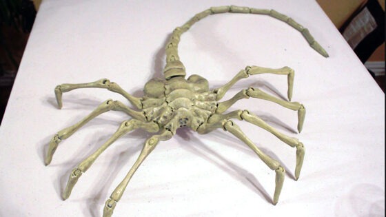
Curtis Socha created the full-size Alien Facehugger as a remix from Julie Sharpe’s adorable mini Facehugger –Seriously, you just want to a keep a couple of those cuties under each armpit don’t you? Mini Facehuggers want to come out to play? “Awwww,” your friends say (while exchanging quick glances with each other and questioning their friendship with you).

Curtis taught himself Blender over three weeks JUST to model this creature until he got it right. There are 10 parts altogether with a recent update of all files -fixed with a run through Netfabb to repair mesh issues (yay!). The model you see here was printed on a Rostock Max V2 and, after assembled, comes in at 40in x 23in – massive!

According to Thingiverse, 83 other users have reported making this, which means there are probably 10 times that many Facehuggers out there, AT LEAST. You can download the life-size Alien Facehugger at Thingiverse.

Have a model you think everyone needs? Share the link and details with us here!

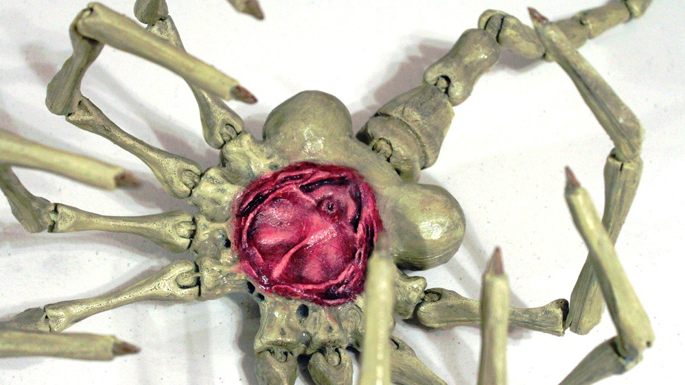
That part of the Facehugger your face wants to avoid.

The post Model of the Week: Life-Size Alien Facehugger [Get it Off!] appeared first on SolidSmack.

Top 3 Onshape Updates: Advanced Search, Flat Pattern, FeatureScript Profiler

$
0
0
onshape-whats-new-features-1703-00

It’s been but a few weeks since the last Onshape update, but once again the Onshape team has locked arms, jumped into the air with a collective shout of “FORM ONSHAPE!” and transformed into a giant robot that opens it chests and delivers another round of new features and updates.

You can see the history and catch the latest updates on the Onshape What’s New page, but we’ve had some interest from readers and discussion around keeping closer track of the Onshape features, breaking down the latest, pointing out our favorites and highlighting the ones we think push ahead product dev for CAD in the cloud.

As usual, we’ll attempt to pick our ‘Top 3 Onshape Updates’ and provide a quick overview of the others. Tell us which one you like the best, which need work, or if we picked the completely wrong features!

The Stats:
Total Updates: 9
Total Updates YTD: 41

Top 3 Onshape Updates (03.27.17)

Advanced Search – Boom! Search within Documents for metadata such as Name, Description, Part Number, State and Revision.

Flat Patterns – Shoom! You can now add flat patterns of sheet metal parts in Assemblies and Drawings.

FeatureScript Profiler – Caachoo! A new built-in profiler (script performance checker) to help optimize your custom features for efficiency and speed.

Other updates

Compare – Now accessible via a new button in the Versions and History flyout.

Surface Finish – Yes, surface finish symbols can now be added to Drawings.

Persistent Drawing Dialogs – Less clicking about. DG&T, Balloon, Callouts and Surface Finish dialogs stay open to place multiple symbols.

BOM Order and Linking – Populate the BOM from bottom to top, place above title block and unlink from BOM app to edit manually.

Projected Views – Projected view activates automatically after first drawing view created. Style of Parent view also respected.

Virtual Sharp – Virtual Sharp style can now be set to either Centermark or Edge Extension.

You can see videos that breakdown each new features here. We’ll be keeping an closer eye on what Onshape is releasing with each update, so let us know what features you’re watching for or want to see the most!

Ask questions and talk about Onshape on SmackTalk!  Our new community site!

The post Top 3 Onshape Updates: Advanced Search, Flat Pattern, FeatureScript Profiler appeared first on SolidSmack.

Model of the Week: Deadpool Bubble Pooter [POOT POWER!]

$
0
0
deadpool-bubble-breezer-01

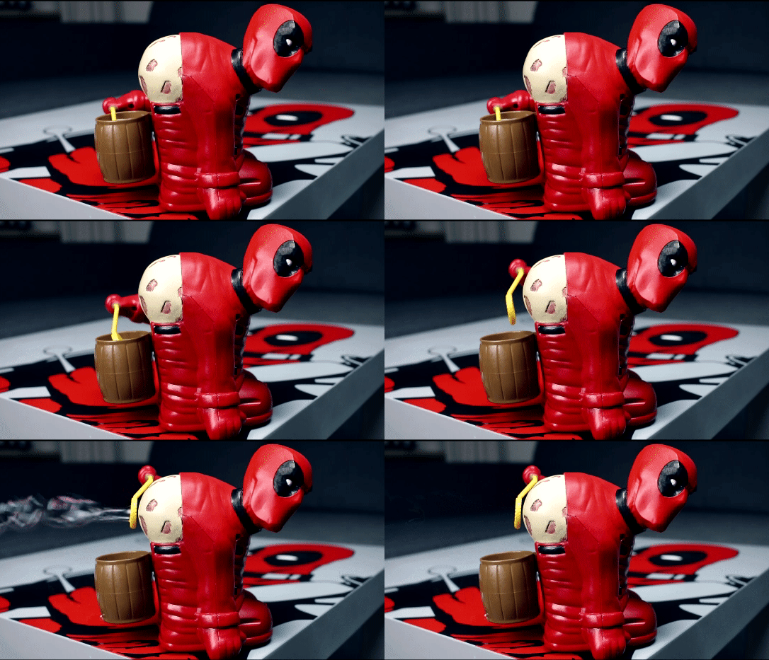
You know what your party DOESN’T have. The ambiance created by a bubble-pooting Deadpool. Yes, folks, this will likely go down in SolidSmack history as either the height or depth of our weekly model feature, but hey, where else can you learn about the coolest design, latest tech AND how to make a Deadpool model that poots bubbles? Yeah, that’s what I thought.

You remember the Deadpool knife block? Well, that brilliance was created by the same Britt Michelsen who has now brought us the official, unofficial Bubble Breezer Deadpool – a mod of a BUB-L Breezer, a shoddy plastic toy of a man bent over, pants down, blowing bubbles out his yoohoo. Let’s just say, Britt’s version is much better, because skin cancer and Deadpool – yep, theeeeere’s the bottom. Here’s what it looks like IN ACTION:

The primary items you’ll need are:
A BUB-L Breezer
Bubble solution
Milliput Modeling Clay (or similar)
Sandable Primer/Filler
Utility knife
Sandpaper
Paint

Unless you want to clay model Deadpool’s head as well, you’ll need to 3D Print Britt’s Deadpool head model. She chopped the head off of this Deadpool model by Nika if you’re intersted in downloading the original model.

There’s a bit of modding, a bit of hacking and a bit of giggling throughout as you realize what you’re making, but it’s a bit of an interesting project in that regard with the improvements Britt explains in the process to reduce noise, fix arm movement and improve airflow for ultimate Deadpool poot bubble enjoyment.

You can download the model and see the step-by-step on Instructables.

Have a model you think everyone needs? Share the link and details with us here!

deadpool-bubble-breezer-02

The post Model of the Week: Deadpool Bubble Pooter [POOT POWER!] appeared first on SolidSmack.

Viewing all 410 articles
Browse latest View live